When we first introduce our insulating cable tray to a customer, the most common question is: "But how much weight can this tray hold?". While our six decades of experience have proven that Unex's know-how is to develop reliable and durable solutions, it is important to explain how we study, test, and validate the technical characteristics of our products.
Therefore, in this article, we will focus on clarifying the maximum weight that Unex cable trays can withstand. Moreover, we can anticipate that Unex cable trays are designed to work at 100% cable filling. But not only that. We will also explain some of the different existing methods for calculating the maximum load of a tray, the tests allowed according to standards, and their differences.
You will see that our insulating cable trays can support a lot.
International standard for cable trays IEC 61537
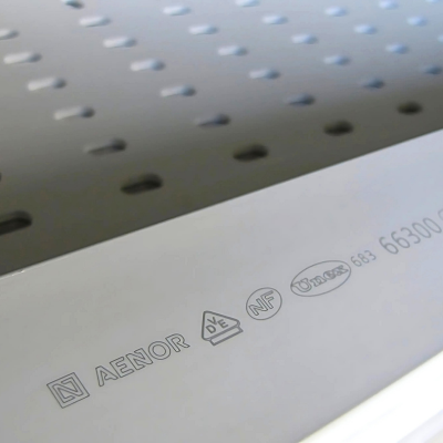
 Let's start with the basics: the international reference standard for cable trays is IEC 61537. Broadly speaking, it describes all the characteristics and different tests that a product must pass to be considered a cable tray.
Among these tests is one we will explore in this article: the test that calculates the maximum load of a cable tray. By standard, this test does not focus on "how resistant the tray is". In other words, at what point the tray breaks. Instead, it focuses on the safe use of the product.
To this end, it defines the concept of a safe working load (SWL). This load is met when the filled tray suffers a longitudinal deflection of more than 1% or a transverse deflection of more than 5%. From that point onwards, the tray is considered to no longer perform its function of supporting cables correctly. Therefore, it has reached its maximum load level.
Once this level is reached, the test continues by adding a further 70% load to ensure that the tray does not break, even if it deflects. In this way, a precise overload is simulated to increase the safety of the installation, as it is verified that the tray will not break despite being loaded with 70% more weight than specified.
NEMA Standard
In countries such as Canada and the United States, there is another type of standard: NEMA. The criterion of this standard is the opposite of the previous one. Here, the load at which the tray breaks is measured, and a safety factor of 50% is applied to indicate the safety working load (SWL). In other words, the trays can be loaded onto half their breaking load.
However, this maximum load can be misleading. If the tray is, for example, made of an elastic material, it can deflect considerably without breaking. This would result in high SWL ratings and the tray would no longer fulfil its task of correctly supporting the cables.
In short, as we have reviewed, there are two standards that seek to standardise criteria for products that are considered cable trays. This can lead to some confusion, and it is common to find manufacturers who provide only NEMA test data, since the loads that are achieved are higher... Or, even, they use tests developed by themselves to obtain their maximum load.
For that reason, comparing loads without confusion between trays is a difficult task for users. This can only be done by real experts. Consequently, manufacturers are always obliged to indicate to which test and standard each piece of information corresponds.
Tests according to IEC 61537: junctions are the key
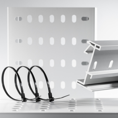
 Going back to the IEC 61537 standard, which is the standard used in Europe, the critical factor in a cable tray installation is the junction between two lengths. Therefore, in the standard, we find different types of tests to calculate the maximum load depending on the location of the junction. Here we explain the most important ones:
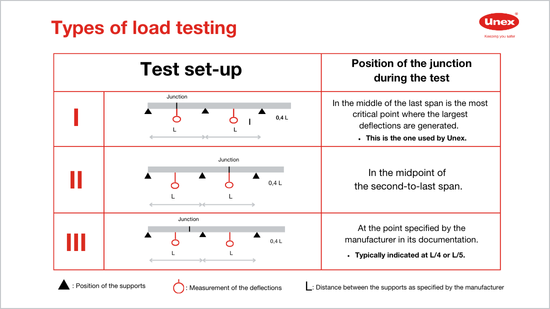
Type I test: several tray lengths are tested and the junction between them is placed at the midpoint of the two supports. At this point, the deflection of the tray is measured because this is the most unfavourable test case. This is the test we choose at Unex for testing our trays, always subjecting them to the worst working conditions to give the best performance.
Type II test: the position of the junction during the test is fixed in the centre of the second-to-last span. For more details, please refer to the table.
Type III test: a number of tray lengths are tested, but the maximum distance between the junction and the support is specified. The distance is typically limited to one-quarter of the distance between the supports. This limitation makes it necessary to check and mount extra supports in the installation. Compliance or non-compliance with this restriction can vary the load of a tray by up to 20%. This method is common among manufacturers who want to give the impression of robustness. However, they need this limitation to achieve values like those of Unex. Anything apart from using the type I test installation method complicates the installers' work considerably.
Considering that it is common to expect a metal cable tray to be strong and able to bear a lot of weight, we, the thermoplastic cable tray manufacturers, have had to rigorously prove that we can compete with metal trays. For this reason, at Unex, we strictly adhere to what the standard stipulates and select the most "unfavourable" method of calculating the maximum load of our trays under the most difficult conditions. This is how the "full load" concept, created by us, was born.
Unex "full load" concept for increased safety
 We know that cable trays are not designed to be "filled to the brim" with cables. But let's face it: as years go by, more and more cables are added, and during installation no one precisely controls the distance of a junction to the support. This is why we, at Unex, created the concept of "full load".
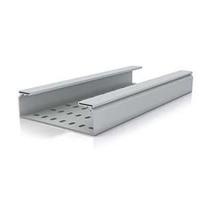
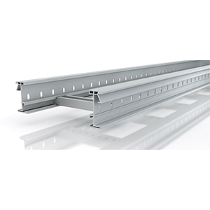
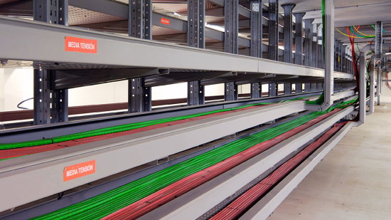
All our cable trays are designed to support as much load as kilos of cable can fit inside them, according to the section of each size and regardless of the junction location. The distance between supports is adjusted according to the working temperature, being between 1 and 1.5 meters for the Insulating Cable Tray 66 and between 2 and 3 meters for the Insulating Cable Ladder 67.
No matter where the junction is, if you use our cable trays, you will have a safe installation. Because safety is our priority. This is confirmed by our claim: "Keeping you safer".
We encourage you to compare the loads. You will see that the Unex insulating cable trays really hold a lot.
If you need help or more information, just contact us!